The theory of vertical movement. The parabolic projectile motion
An object thrown in the air, near the earth’s surface, moves along a parabolic path under the action of gravity only. The only force of significance that acts on the object is gravity, which acts downward to cause a downward acceleration. Because of the object’s inertia, no external horizontal force is needed to maintain the horizontal motion. (Wikipedia).

A classic example of this motion, showing clearly the trajectory, is the parabolic flow of water:

The projectile motion trajectory can be theoretically defined based on the Galileo Galilei equations of motion and, if the air friction is insignificant compared with the other forces acting on the projectile, it can be defined by the following parabolic equation:
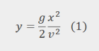
Where:
- g – the gravitational acceleration
- t – the time
- v – the horizontal speed
- x – the horizontal distance
- y – the vertical distance
Since the projectile movement is defined by g, the gravitational acceleration, any particle located inside the projectile will experience imponderability relative to the projectile local inertial reference system. In this case there is practically a 100% reduction of the gravitational acceleration relative to this local reference system.
Based on this principle there are airplanes that fly for short periods of time on the parabolic trajectory defined by (1), sometimes named “the zero g parabola”. When are following this trajectory, these zero-g planes can provide short periods of imponderability.
Although there are on web a few nicer examples of persons experiencing imponderability in these planes, I am illustrating this here with Stephen Hawking’s experience of it:

Stephen Hawking enjoys zero gravity parabolic flight at the celebration of his 65th birthday on 8th January 2007 (source of the image Wikipedia)
What has this to do with the vertical curves used in transportation alignment design?
Well, a lot. This is the main justification of the curve type used in the design – the vertical parabola. Also, based on the same Galilei equations of motion we can define limits for these vertical curves, limiting the vertical acceleration experienced inside of a vehicle moving along the vertical curve.
Probably, dear reader, when driving over a steep road hump, you have experienced something similar to this imponderability phenomenon. Sometimes after passing the hump peak point, if the speed is high enough and the hump profile is close to the parabola we are talking about here, the driver experiences a floating sensation, due to the significant reduction in g.
This principle is used to design roller coasters, where the riding alignment is designed in such a way to provide controlled variation of the vertical (and lateral) acceleration to entertain the riders and still keep a safe (and almost comfortable) riding.
The limits of vertical acceleration
As you can imagine, the condition to provide safe riding in railway track design is to limit significantly the maximum reduction (or increase) of the gravitational acceleration. The safe limit is usually set around 6% of g – hence the passenger would experience at least 94% of the gravitational force. Sorry, no chance of imponderability on railways!
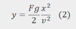
The vertical parabola is then defined based on this F% reduction percentage of g, as:
Due to the fact that the track gradients are small, in railway design it is accepted the approximation defined by the osculating circle of the parabola – the tip area of a parabola can be defined by a circle and it can have an assigned radius – Rv (see here the explanation on the osculating circle here). Taking this into consideration, we have:
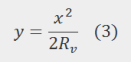
From (2) and (3) we are getting:

Converting all the parameters to their normal units:
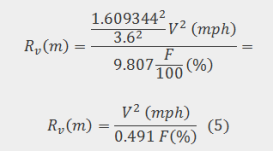
The latter equation is the one that defines the radius Rv of the vertical parabola, based on the F% reduction of the gravitational acceleration.
In the United Kingdom the limits for this F% reduction/increase of the gravitational acceleration are defined in the “Vertical Curves” chapter of the Track Design Handbook – NR/L2/TRK/2049.
These limits are:
- Normal limit – 2.25% g
- Maximum for a hollow – 3.25% g
- Maximum for a hump – 4.25% g
- Exceptional – 6.00% g
References:
Cope, Geoffrey H., ed. (1993) British railway track: design, construction and maintenance, Permanent Way Institution.
NR/L2/TRK/2049 ( 2010) Track Design Handbook, Issue 12, Network Rail.


If your standards have rules for correlating the two, allowing this interpretation, yes. Otherwise, I would say no.
But don’t trust a blogger.
LikeLike
Hi Constantin, what about if I have a crossover which has existing deficiency of 85mm (max for my railway) but is located wholly on a vertical curve of lets say 6000m Equivalent radius. The vertical acceleration would thus increase my cant deficiency over the limit, right?
LikeLike
Hi Ricardo. That comes from the movement of an object in a gravitational environment. See the wikipedia link – it explains it well.
LikeLike
Question how do you get the initial formula y=(gx^2/2v^2)? Thanks
LikeLike
Q
LikeLike
Good work done. Your discussions are very helpful
LikeLike