INTRODUCTION
In transportation infrastructure design the route is defined based on its axis (centreline) – the alignment model. This simplified abstract model is designed in such a way to clearly define the principle course of the infrastructure project.
For most of the transportation means the infrastructure alignment design is split into two main two-dimensional complex strings: the horizontal alignment and the vertical alignment.
The horizontal alignment consist of three types of elements:
- Line segments – straights
- Circular arcs
- Transition curves
The movement of the transportation vehicle over circular elements is generating lateral accelerations, dependant on the speed of the vehicle and on the radius of the curve. In order to avoid the sudden change of these accelerations when passing from a curve to a different curve or a straight, the horizontal alignment includes transition curves. These curves have a continuous variation of curvature, ensuring the smooth transition between the horizontal alignment elements of constant curvature.
The most well-known transition curve is the Clothoid. In its real world application the clothoid enables a car driver to ride smoothly by turning the steering wheel with a constant speed, defining a clothoidal spiral, a continuous and linear curvature variation.
A curve with so many names …
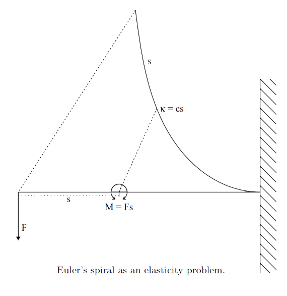
The clothoid equations were first defined by Leonhard Euler; this is why, in general Physics the curve is often called Euler spiral. The French physicists Augustin-Jean Fresnel and, later, Alfred Cornu, rediscovered the curve and defined its parametric equations – hence the curve is sometimes called Fresnel or Cornu spiral.
(source of the image: Levien, R. (2008) The Euler Spiral: A mathematical history.)
In 1890, Arthur N. Talbot, Professor of Municipal and Sanitary Engineering at the University of Illinois, defined for civil engineering the “railway transition curve” (Talbot – 1912), with similar equations as Euler did for elasticity and Fresnel and Cornu for optical applications.
The name clothoid was suggested by the Italian mathematician Ernesto Cesàro. The word clothoid comes from klothos, the Greek word for spin (wool) the shape of the curve thread that wraps around the spindle. The same root appears in the name of Clotho (The Spinner), one of the three Fates who holds the thread of human destiny.
Clothoid geometry and (some) math
The clothoid equations can be defined starting from the condition of linear relation between radius and length:
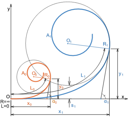
This defines an infinite spiral, starting from the origin (x=0, y=0, R=∞, L=0) and spinning in two infinite loops to two points where R=0 and L=∞:
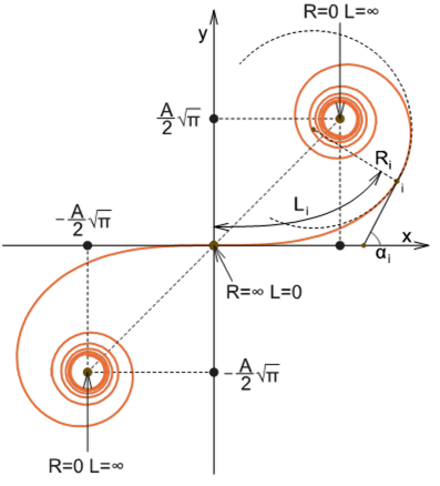
The constant A is called flatness or homothetic parameter of the clothoid.

The clothoid coordinates and the majority of the other characteristic elements of the spiral can be defined based on this essential parameter. For example, the clothoid curvature gradient is 1 in A².
In road design, an alignment developed to have all the transitions with practically the same A is seen as an optimum design, providing similar comfort conditions from the point of view of the variation of the lateral acceleration across all the transitions of that route. Some of the national road design standards are considering this criteria together with superelevation and aesthetic conditions (TAC – 2009).
In railway design an alignment developed with constant A is providing constant rate of change of the Equilibrium Cant (the sum of the rates of change of cant and cant deficiency). If this is done together with a constant E/D ration across all the curves, that alignment will provide practically the same comfort conditions over all the transitions and also similar wear conditions for top of railhead.
The angle αi , measured between the tangent in the current point i of the clothoid and the initial direction (where R = ∞), is called direction angle and is computed dependant on the length of the clothoid arc to the current point Li , and the current radius Ri :

where L is the total length of the clothoid and R its final radius.
The Cartesian coordinates of the clothoids can be defined starting from the above equation; using Euler (Fresnel) integrals for sine and cosine, these coordinates are:
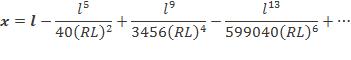
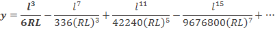
Both equations have infinite terms. For railway track and road design, only a part of the clothoid can be practically used – the arc starting from origin to the area where the deflection angle α ≈ 90°.
For this section of the clothoid arc the first 4 terms of the equations provide sufficient accuracy to allow the site tracing of the transition curve.
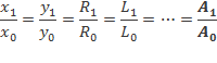
Before the introduction of the Computerised Aided Design (CAD) in the alignment design for road and railway, the clothoid coordinates were computed based on a set of tables defined for a reference clothoid (usually the one defined by Aₒ = 100) and using the following relation:
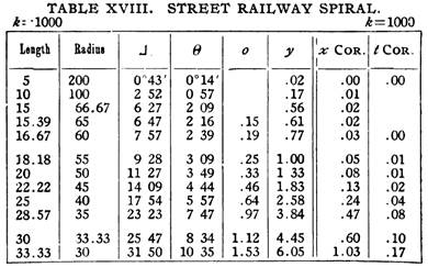
A snapshot from Talbot, A. N. (1912) The Railway Transition Curve.
Any other clothoid can be defined based on this property (called homothety relative to the origin O) :
Another option largely used was to consider only the first term of the x and y equations, defining in this way the cubic parabola, a close approximation of the clothoid.
Clothoid shift
As the clothoid spiral develops, the circle defined by the radius R is gradually shifted away from the x axis. This shift is defined as:
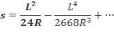
The first term of this equation defines the shift for the cubic parabola.
(to be continued)
Later edit: (09/10/2016) The direction angle equation was added based on the blog comments.
References:
Cope, G. (1993) British Railway Track – Design, Construction and Maintenance. Permanent Way Institution, Echo Press, Loughborough.
Racanel, I. (1987) Drumuri moderne. Racordari cu clotoida. (Modern roads. Clothoidal transitions). Editura Tehnica, Bucharest. Romania.
Levien, R. (2008) The Euler Spiral: A mathematical history. University of California at Berkeley. (report available online on digitalassets.lib.berkeley.edu)
Radu, C. (2001) Parabola cubica imbunatatita (Improved cubic parabola). Technical University of Civil Engineering Bucharest.
Radu, C., Ciobanu, C. (2004) Elemente referitoare la utilizarea parabolei cubice imbunatatite (Elements related to the use of the improved cubic parabola). Third Romanian National Railway Symposium, Technical University of Civil Engineering Bucharest. Romania.
Talbot, A. N. (1912) The Railway Transition Curve. Fifth Edition. Engineering News Publishing Co. New York. (available online on archive.org)
TAC (2009) Geometric Design Manual for Canadian Roads. – Volume 2. Transportation Association of Canada


Hi Mahmood. The cubic parabola is a simplification of the clothoid – by selecting only the first term of the equation for X and Y. For track/road geometry that is Y = X³/(6RL). I don’t want to comment here the section B.1.1 of the design handbook. But as you can see there, the actual formula for cubic parabola is this one I quoted. Check the older versions of that section.
LikeLike
HI Constantin, Could you be able to explain me the Cubic Parabola method K=Kx3, where K is a constant and the slope curve is Dy/Dx = 3Kx2. An example with a solution would be ideal. You can refer to section B.1.1. Form of Transition Curve in Track Design handbook 2049. Also would be interested if you could provide some examples of Permanent Way Mathematics.
LikeLike