The good old times
Since the early beginnings of the railway, the track engineers were aware of the centrifugal forces influence to the train riding when passing through a curved section of track. To compensate this influence, the track was inclined laterally by creating a positive level difference between the outer and inner rails of a curved track. This inclination is called cant or superelevation.
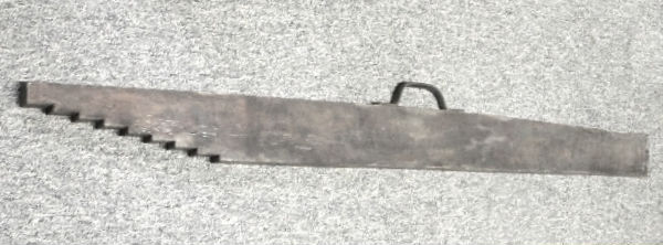
Since then, the cant is measured as the level difference between the rail heads. In the picture below is shown an old measuring device device, showing a 5 inch cant. The level difference was reported to a horizontal reference defined by a spirit level. This principle of measurement, refined and modernised, is still in use today in almost all the guided systems of transport.

Railroad track spirit level in place indicating 5″ of superelevation between the inside and outside rail of a curve along the Keystone Corridor near Narberth, PA. (Source of the image – Wikipedia)
Here is a picture of another old cant measuring device using spirit level and a 20mm stepped cut wood plank:
Old cant measuring device
The theory
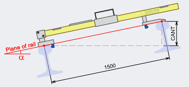
The permanent way engineering theory behind the definition of cant was explained briefly here, in an older post: Cant and Cant Deficiency. Where is the 11.82 coming from?
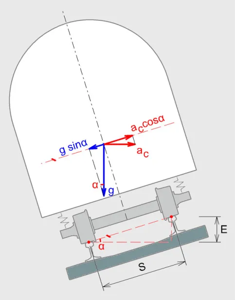
The the cross-level angle, α , and the cant reference definition.
The main thing to consider, from the point of view of understanding how the cant is measured, is that all the cant parameters (cant, deficiency, rates of change of cant and cant deficiency, cant excess, non-compensated lateral acceleration etc) are defined based on the track cross-level angle, α . If this angle is kept constant, all the cant parameters do not vary. They will stay the same, no matter how the track cross level elements and dimensions vary, as long as the cross-level angle does not change.
For a few guided transport systems (e.g. maglev, monorail) this inclination angle, α, is used directly to express the cross-inclination of the infrastructure support system. For railway and tramway track the angle is converted to a length dimension – the cant, E, expressed in mm.
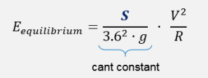
The cant value, E, is directly related to the reference base S, used to define the cant constant:
Around the world, there are a few versions of the nominal value for normal gauge: 1435mm (what we generally call “normal track gauge”) ,1432mm, 1433mm, 1438mm. There are also different types of rails – with different rail head profiles and head width. The rails are placed on track with different inclinations: vertical (for switches and crossings), 40:1 (in Germany) or 20:1 (the most common rail inclination). For tramways, some of the rails are installed vertical and the inclination is embedded in the grooved rail head profile.
Due to all these factors there are a wide range of track layouts that can provide the same track cross-level angle, α. But, as we saw above, the same angle should always mean the same cant. Hence, it was required to define a constant cant reference base, S, one that is independent of the different factors mentioned above and provide for the same track inclination the same cant value. This constant cant reference base, S, can also provide a coherent and unified calibration method for the cant measurement devices. All these devices are measuring the track inclination angle, α, reported to a horizontal plane. This horizontal plane is defined by spirit level (for almost all the hand held measuring devices), balancing weights (for old track maintenance machines) or gyroscopes (used by modern measuring and maintenance machines).
Taking into consideration the factors mentioned above, UIC (International Union of Railways) has conventionally established for normal track gauge the cant reference base S to be 1500mm. This was initially based on the the wheel/rail theoretical contact points distance for the most used rail at the time – S49 (the one called now CEN49E1). But, as we can understand from all the things mentioned here, this is just a convention and is independent of rail type, rail inclination, gauge variance etc.
The Standard defining the cant measurement
The way to measure the cant is currently standardised in the European Norm (BS) EN 13848-1: Railway applications — Track — Track geometry quality — Part 1: Characterisation of track geometry:

Cross level definition in EN 13848-1 (Figure 5)
4.4 Cross level
4.4.1 Definition
The difference in height of the adjacent running tables computed from the angle between the running surface and a horizontal reference plane. It is expressed as the height of the vertical leg of the right-angled triangle having a hypotenuse that relates to the nominal track gauge plus the width of the rail head rounded to the nearest 10 mm (refer to Figure 5).
NOTE:
For nominal gauge of 1435 mm the hypotenuse is 1500 mm in length.
For nominal gauge of 1524 mm the hypotenuse is 1600 mm in length.
For nominal gauge of 1668 mm the hypotenuse is 1740 mm in length.
measuring CANT
The most used cant measuring device is the track gauge.
To measure the gauge the tool requires its measuring pads to be in contact with the rail running edges, at 14mm below plane of rail:
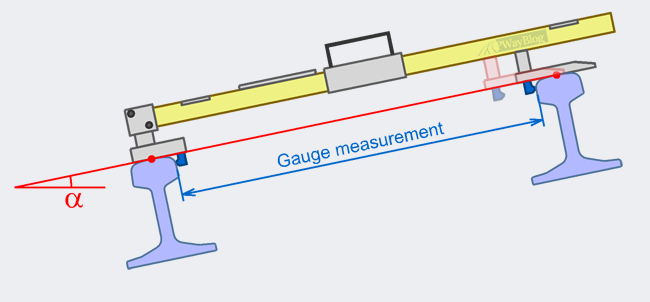
Track gauge device – gauge measurement
To measure the cant it is sufficient to place the two pads on the rail heads, allowing the device to have the plane of rail defined (see the image below). Although the sliding pad used to measure the gauge is usually in contact with the running edge of the rail, this is not a mandatory condition to provide a correct measurement of the cant.
The modern cant measuring devices, as well as the old ones, are not considering the gauge, as nominal value nor its variance, when measuring cant.
Track gauge – measuring cant
Can we check this?
This can be checked easily:
Place the track gauge device on two canted rails or on an inclined surface and measure the cant for this specific inclination.
Keeping the same inclination angle, α , vary the “track gauge” by moving the mobile sliding pad used to measure gauge (see the figure above).
If the device is correctly calibrated the cant will be shown the same as the initial one, not being influenced in any way by any kind of gauge variance, as long as the inclination angle is kept constant.
No matter if the gauge is 1432mm, 1435mm, 1438mm, or any other such value, no matter the rail type or rail inclination, for the same track inclination angle α, the cant shown by any officially approved and well calibrated measuring device will the same, always reported to a 1500mm base reference (the hypotenuse mentioned in the European Norm).
References
- BS EN 13848-1: Railway applications — Track — Track geometry quality — Part 1: Characterisation of track geometry. BSI Group, London 2003
- Volker Matthews: Bahnbau. 4. Aufl. B.G. Teubner Stuttgart / Leipzig 1998


Pingback: Demiryolu Hat Geometrisi: Cross Level (dever) – Elvan ARSLAN
It should not. In fact that is a way to check if the track gauge is correctly calibrated. But there arw old ones that have only one side for significant cant values. For those it matter.
LikeLike
Does it matter what way the can’t stick is when measuring can’t
LikeLike
The 1:40 and 1:20 define the rail inclination angle from vertical (or plane of rail for canted track) towards the track centre.
From the point of view of the cant measurement this inclination is not relevant. As the rails are both inclined, the plane of rail remains the same.
LikeLike
how is the definition/ measurement of 1:40 or 1:20 ?
LikeLike
Where does 3.6 comes from when calculating RCC and RCD values?
LikeLike