A railway vehicle moving along a circular curve is subjected to an inertial centrifugal acceleration (ac), directly proportional with its speed and in reverse proportion with the curve radius. This lateral acceleration is perceived by the passengers as an uncomfortable sensation and, above a certain limit, endangers the lateral stability of the running vehicle. In order to compensate at least a part of its effect, when this centrifugal acceleration reaches a certain limit, the track is inclined towards the centre of the curve with the cross-level angle α (see figure 1).
The traditional way to measure this inclination is the cant, E, defined as “the vertical difference in heights of the two rails of a track, measured at centerline of the rail heads (S)” (NR/L2/TRK2049 – 2010, Track Design Handbook, B.1.1).
When this inclination is applied, the gravitational acceleration g will generate a parallel component with the plane of rail, compensating a part of the centrifugal acceleration.
 Figure 1. The non-compensated lateral acceleration
In railway alignment design the complex dynamic behaviour of the vehicle is simplified to simple equations in order to define easy to understand and apply design parameters and standard limits. This simplification takes out the differences between the suspended and un-suspended mass, the suspension behaviour, the lateral and vertical thrust of the vehicle, the bogie attack angles, the vehicle acceleration or braking – to mention only a few main elements. The general standard rules for alignment design consider the vehicle a material point moving with constant speed at low rail level, along the centerline of the track.
The limits of the track alignment design parameters are in such a way defined to compensate for this simplified but easy to use approach. These limits are carrying safety factors, dynamic conditions and other constraints to ensure a safe and comfortable riding.
Taking into account all these simplifications accepted by the design standards, the final, non-compensated lateral acceleration of the vehicle, seen as a material point, can be considered:
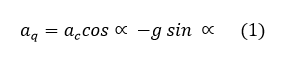
The cross-level angle α is small, hence cos α is considered 1. The equation (1), with acceptable precision, becomes:
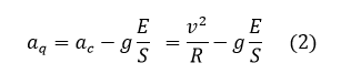
where:
v is the speed of the vehicle (m/s)
R is the curve radius (m)
g is the gravitational acceleration (m/s²)
E is the applied cant (mm)
S is the cross-level standardised reference for rail heads centerline distance (mm) (see European Norm EN13848 – Track Geometry Quality). In UK this is conventionally considered to be 1502mm. (Cole, 1993, British Railway Track).
This equation allows to define the cant and all its related parameters, established to limit the non-compensated lateral acceleration.
Most of the track standards around the world (the British Track Design Handbook, TRK/2049 included) are using the concept of Cant Deficiency, D, instead of non-compensated lateral acceleration aq.
The Cant Deficiency is derived from (2) and defined as:

The factor 11.82 is defined for normal gauge and takes into account g, S and the speed unit conversion from m/s to km/h.
An important fact to understand and consider is that this cant constant value – 11.82 is a conventional figure. It is defined based on a presumed conventional rail centerline distance of 1502mm, for normal gauge track and it is related to the standardised way of measuring the cant, defined in the European Norm EN13848 – Track Geometry Quality.
It is established based on general equations and it’s not defined dependant of rail type or gauge variance (as long as the track has a normal track gauge).
That is why this constant should not be changed based on the variance of the normal gauge and kept the same for a gauge of 1432mm, 1435mm, 1438mm.
The cant constant carries with it all the simplifications mentioned above. Due to these simplifications, its around the world generalised value for normal gauge is 11.8 – an acknowledgement of the level of precision used to define it.
Also, as was demonstrated above, the cant constant is computed and based on the conventional rail centerline distance (considered in UK to be 1502mm) and not on gauge (1435mm). The difference between the two is significant and considering the later when defining the cross-angle in causing a significant error in cross level and cant.
This error is sumarised in table 1.
| cant (mm) | cant error (mm) |
| 0 | 0.0 |
| 25 | 1.2 |
| 50 | 2.4 |
| 75 | 3.7 |
| 100 | 4.9 |
| 125 | 6.1 |
| 150 | 7.3 |
Table 1. Cant error when is presumed computed based on gauge instead of rail centerline distance.
The error becomes even more significant when is propagated over sixfoot for siding geometry or for canted S&C design.


Oh, that is very true – on site a few mm out (geometrically speaking) very often don’t mean a thing.
What this post is about is a design principle. From design perspective we should try to be as precise as our tools allows us.
If the designer is negligent because “a few mm don’t really matter”, those millimetres will be consumed from the installation tolerance the contractor has. And the contractor’s tools are not as precise as the ones the designer has.
The other thing here is that very often some designs are not accepted because of a few millimetres – and if that is an acceptable thing to happen then at least the few millimetres between an approved and rejected one should be the right ones and not on the ones that are not justified by first principles.
LikeLike
All well and good, yet avoid getting bogged-down in the detail… I wonder how many correspondents might have ‘walked’, surveyed, designed, “deep-dug”, set out, re-laid, stressed, inspected and trained/mentored inspection staff on over 5,000 MILES of track in just over 50 years? A few mm “out” from design values here and there will not amount to one “jot” of difference (or any significant increase in risk) regarding track quality, passenger comfort or safety – just so long as changes in or made-to track ‘geometry’ are never allowed to be(-come) sharp… Plenty of Track Standards to download for free and compare and consider, such as ‘RGSonline’, never forgetting RAIB’s extremely well-produced reports on “Things That Go Bump In The Night” (or day!).
LikeLike
Mahmood, see the end of my post here: https://pwayblog.com/2016/01/25/how-is-the-cant-measured/
“Place the track gauge device on two canted rails or on an inclined surface and measure the cant for this specific inclination.
Keeping the same inclination angle, α , vary the “track gauge” by moving the mobile sliding pad used to measure gauge (see the figure in the post).
If the device is correctly calibrated the cant will be shown the same as the initial one, not being influenced in any way by any kind of gauge variance, as long as the inclination angle is kept constant.
No matter if the gauge is 1432mm, 1435mm, 1438mm, or any other such value, no matter the rail type or rail inclination, for the same track inclination angle α, the cant shown by any officially approved and well calibrated measuring device will the same, always reported to a 1500mm base reference (the hypotenuse mentioned in the European Norm).”
LikeLike
No, the cant constant is a standard defined parameter. It is not influenced by gauge variations. In my opinion the constant should be 11.8 as defined by the European Norm. The cant is in fact an angle, its conversion to mm level difference is not made on particular values of gauge but on a standard base of 1500mm – see my other post “how is cant measured”
LikeLike
Hi Constantin, Could you confirm that the following ‘Equilibrium constant’ (EC) equation has been used correctly to give 11.82? I have worked out as follows:
S/g x SU^2 1502/9.80665 x 3.6^2, where S is the rail to rail centre gauge, g is gravitational acceleration and SU is Speed unit 3.6. Note: 1502 is the UK standard gauge
The answer is 11.818 ~ 11.82. (1432mm) 70mm Rail
I’m not sure if its 11.84 , for 1505 (1435mm, 70mm Rail.
Does it make a difference with either 11.84 or 11.82?
LikeLike
I used this formula 1km/h = 1000 / 3600 m/sec = 5/18 m/sec. For example 45mph (72.42048) km/h x 5 =362.1024. 362.1024 / 18 = 20.1168. The formula you have provided is the same as well. Thanks Constantin. Much appreciated.
LikeLiked by 1 person
The Speed V is in km/h.
When this is converted to m/s it turns into
V(m/s) = V(km/h) *1000(m/km)/3600(s/h) = V(km/h) /3.6
LikeLike
Where does the 3.6 comes from when working out Rate of Cant Change RCC?
LikeLike